where k is the wavenumber
What does the diffraction pattern of a star look like and what is the
limit of a telescope's resolution? For wavefunction ![]() at point P in the imaging plane, the Fraunhofer diffraction integral is
at point P in the imaging plane, the Fraunhofer diffraction integral is
![]()
where k is the wavenumber ![]() ,
, ![]() and
and ![]() are the aperture's width and height, R is the distance from the aperture's
center to P, x and y define the position of P on the image plane,
are the aperture's width and height, R is the distance from the aperture's
center to P, x and y define the position of P on the image plane, ![]() = x/R and
= x/R and![]() = y/R. Since telescopes generally have circular apertures, we will let
a be the radius of the aperture and write
= y/R. Since telescopes generally have circular apertures, we will let
a be the radius of the aperture and write ![]() ,
, ![]() ,
, ![]() and
and ![]() in cylindrical coordinates where the z axis is the axis of the telescope.
in cylindrical coordinates where the z axis is the axis of the telescope.
In the aperture plane,

In the image plane,

If ![]() ,
the angle between the axis of the telescope and R, is small,
,
the angle between the axis of the telescope and R, is small,
![]()
and
![]()
We can choose ![]() because of the cylindrical symmetry of the telescope. Therefore, equation
1 becomes
because of the cylindrical symmetry of the telescope. Therefore, equation
1 becomes
![]()
We are only concerned with the real part of this integral so
![]()
The Bessel function ![]() is defined as
is defined as
![]()
and
![]()
This means equation 10 can be written as
![]()
with ![]() ,
where f is the focal length of the telescope.
,
where f is the focal length of the telescope.
The intensity pattern due to the constructive and destructive interference
is related to ![]() by
by

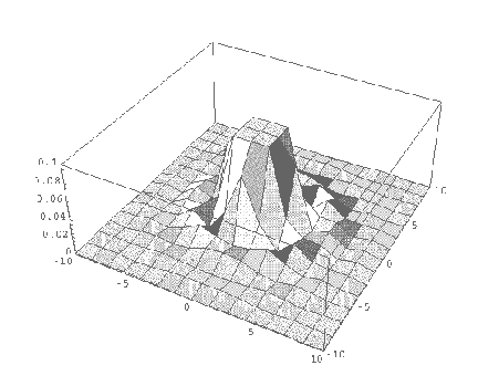
This intensity pattern of constructive and destructive interference
rings is known as the Airy diffraction pattern (Figure 1), named after
Sir George Airy, the Astronomer Royal of England who first derived it. ![]() of the total intensity is located within the central circle or the Airy
disk. The dark destructive interference rings occur at the minimums of
of the total intensity is located within the central circle or the Airy
disk. The dark destructive interference rings occur at the minimums of ![]() ,
where u = 3.83, 7.02 ... or
,
where u = 3.83, 7.02 ... or ![]() ...
...

The limit for the telescope's resolution is set by the diffraction at
the aperture of the telescope. For a point source, like a star, the resulting
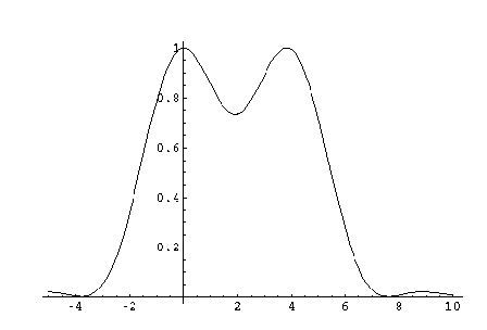
image is a Airy pattern. The Rayleigh criterion for resolution of two point
sources is that the central maximum of one images lies at the first minimum
of the second image (Figure 2). Thus the limit of the angular resolution
is
![]()
The Airy disk has angular radius![]() so the radius of the central disk
so the radius of the central disk
![]()
(Heald and Marion, 1995; Hecht, 1987; Jackson, 1962).
